FFI0600-2011
Description
Wall-mounted light switch client with 6 inputs and integrated WiFi.
Status: Active
Hex: 0x06002011
Number of Inputs: 6
Number of Outputs: 0
Form Factor: Wall-mounted
MCU
AI-Thinker ESP-12F (ESP8266) with 4MB flash and integrated 2.4GHz WiFi
Inputs
6 switch connectors (SW1–SW6), each a 4-pin JST XH header.
RJ-45 Pinout
Each unit supports up to 6 buttons/switches via two RJ-45 jacks (4 channels on the primary, 2 on the secondary). Devices are powered over the Cat6 cable from the Controller.
Not Ethernet
The RJ-45 jacks carry DC power and direct channel signals, not Ethernet. WiFi is used only during initial provisioning and for OTA firmware updates.
Primary Jack
| Pin | Wire Color | Usage |
|---|---|---|
| 1 | White/Orange | Channel 1 |
| 2 | Orange | Channel 2 |
| 3 | White/Green | Channel 3 |
| 4 | Blue | +12VDC |
| 5 | White/Blue | +12VDC |
| 6 | Green | Channel 4 |
| 7 | White/Brown | Ground |
| 8 | Brown | Ground |
Secondary Jack
The secondary jack uses only pins 1, 2, 7, and 8 (channels 5–6, power, and ground).
| Pin | Wire Color | Usage |
|---|---|---|
| 1 | White/Orange | Channel 5 |
| 2 | Orange | Channel 6 |
| 7 | White/Brown | Ground |
| 8 | Brown | Ground |
WiFi
Connectivity is provided by the ESP-12F module's integrated 2.4GHz WiFi antenna.
Bill of Materials
Prices are each, USD, exclusive of tax/tariff, or assembly prices.
| Use | Manufacturer | Manufacturer Model | Supplier | Supplier Part Number | Purchase Price | Notes |
|---|---|---|---|---|---|---|
| Master Control Unit | AI-Thinker | ESP-12F | ESP8266, 4MB flash, integrated WiFi | |||
| 3.3V Power Regulator | XLSEMI | XL1509-3.3E1 | SOP-8 | |||
| Schottky Diode | SK32WA | SOD-123F | ||||
| Switch Connector | JST | B4B-XH-A(LF)(SN) | 4-pin, qty 6 | |||
| Primary Connector | CONNFLY Elec | DS1128-06-S8B0P-X | ||||
| Secondary Connector | CONNFLY Elec | DS1128-06-S8B0P-X | ||||
| 10kΩ Resistor | R0402, qty 5 | |||||
| 1µF Capacitor | C0402 | |||||
| 330µF Capacitor | ||||||
| 470µF Capacitor | ||||||
| 33µH Inductor |
Reference Designs
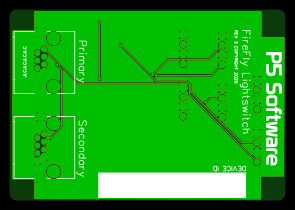
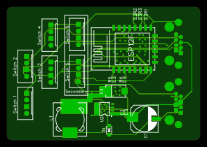
3D Printed Parts
| Type | Buttons | Download |
|---|---|---|
| Faceplate | 1 | Download |
| Faceplate | 2 | Download |
| Faceplate | 3 | Download |
| Faceplate | 4 | Download |
| Faceplate | 6 | Download |
| Adapter Plate | Standard | Download |
| Adapter Plate | 4 Button | Download |
⚠️ Known Issues and Defects
The following are known issues (and in some cases their improvements) with this hardware.
- No antenna cutout on PCB.
- PCB lacks flash headers.
- PCB lacks flash button.
- PCB traces are small.